
The Agra Dot Energy Sovereign Power System: Standardized Module Catalog
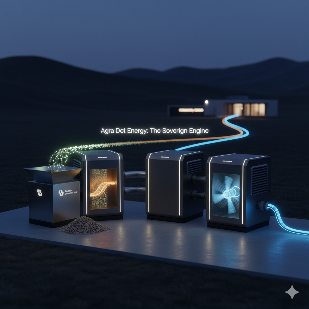
Here is a detailed list and description of the standardized, containerized, “plug-and-play” modules that constitute the Agra Dot Energy Micro GTL System.
The Agra Dot Energy Sovereign Power System: Standardized Module Catalog
Design Philosophy: The Agra Dot Energy system is engineered on a principle of radical modularity. Each stage of the waste-to-energy process is housed within a standardized, containerized module designed for rapid transport, simple on-site interconnection, and scalable deployment. This “System-in-a-Box” approach dramatically reduces engineering costs, shortens lead times, and ensures predictable, reliable performance.
All modules are interconnected via standardized mechanical and data interlinks (quick-connect flanges and armored fiber-optic umbilical cords), allowing a complete power plant to be commissioned in a fraction of the time required for traditional construction.
Core Process Modules
Reciving Feedstock
- Purpose: To receive, prepare, and homogenize raw biomass feedstock for optimal gasification. This is the critical input stage that ensures process stability.
- Form Factor: Standard 40ft High-Cube Shipping Container, with a large top-loading hopper.
- Key Hardware:
- Primary Shredder/Grinder: Reduces the size of incoming biomass (wood chips, corn stover, etc.) to a uniform consistency.
- Rotary Drum Dryer: Utilizes waste heat captured from the power generation module to reduce the moisture content of the feedstock to the ideal percentage.
- Automated Conveyor System: Transports the prepared feedstock from the dryer to a sealed output chute.
- Plug-and-Play Interfaces:
- Input: Open-top hopper for loading raw biomass.
- Output: Standardized, sealed mechanical chute for connection to the Gasification Core.
- Data: Armored data link to the Central Control module.
- Power: Standardized 480V 3-phase power input.
plasma gasification
- Purpose: The heart of the system. This module uses plasma gasification to perform the molecular disassembly of the prepared feedstock into clean, energy-rich synthesis gas (syngas).
- Form Factor: Reinforced 40ft High-Cube Shipping Container with advanced thermal and acoustic insulation.
- Key Hardware:
- Plasma Reactor Vessel: A vertically oriented, high-strength steel vessel lined with a multi-layer, high-purity alumina-zirconia refractory.
- Transferred Arc Plasma Torches (x2): Redundant, water-cooled graphite electrode torches designed for high-efficiency energy transfer and long operational life.
- Torch Power Supply Unit (PSU): A solid-state, high-amperage power supply that drives the plasma torches.
- Vitrified Slag Removal System: An automated, air-locked port at the base of the reactor for the safe removal of the inert, glass-like byproduct.
- Plug-and-Play Interfaces:
- Input: Sealed feedstock input flange from the FP-100.
- Output: Insulated, high-temperature syngas output pipe.
- Data: Armored data link to the Central Control module.
- Power: High-voltage DC input from the PSU.
catalytically convert to Sustainable Fuel
- Purpose: To purify the raw syngas and catalytically convert it into high-grade, liquid synthetic fuel.
- Form Factor: Standard 40ft Shipping Container with extensive external piping and heat exchangers.
- Key Hardware:
- Syngas Scrubber & Filtration System: A multi-stage system that removes particulates, tars, and any unwanted chemical compounds from the raw syngas.
- Fischer-Tropsch Slurry Reactor: A cobalt or iron-based catalyst is suspended in a liquid wax medium. The purified syngas is bubbled through this slurry, where the catalytic conversion to liquid hydrocarbons occurs with superior heat management.
- Catalyst Management System: An automated system for storing, adding, and filtering the catalyst.
- Plug-and-Play Interfaces:
- Input: Raw syngas input from the GC-200.
- Output: Conditioned liquid fuel output pipe.
- Data: Armored data link to the Central Control module.
- Power: Standardized 480V 3-phase power input.
Distribution and Logistics
- Purpose: To store the synthetic fuel and convert its chemical energy into reliable, grid-quality electricity.
- Form Factor: Standard 40ft Shipping Container with a roof-mounted, attachable exhaust stack and large side ventilation louvers.
- Key Hardware:
- Synthetic Fuel Day Tank: A climate-controlled, double-walled tank that stores a ready supply of the liquid fuel produced by the SC-300.
- High-Efficiency Power Generation Turbine: A compact, industrial-grade gas turbine optimized to run on the specific synthetic fuel produced by the system.
- Waste Heat Recovery System: Captures thermal energy from the turbine’s exhaust to provide heat for the FP-100’s drying process.
- Plug-and-Play Interfaces:
- Input: Liquid fuel input from the SC-300.
- Output: High-amperage, insulated busbars for power output.
- Data: Armored data link to the Central Control module.
Balance of System (BOS) Modules
- Purpose: The intelligent “brain” of the entire system. It houses the control hardware and software that automates, monitors, and optimizes the entire process.
- Form Factor: Climate-controlled 20ft Shipping Container, acting as a clean, on-site command center.
- Key Hardware:
- Rack-Mounted Industrial Servers: Running the proprietary Agra Dot AI-powered process control software (the “digital twin”).
- Industrial-Grade UPS: Provides uninterrupted power to the control system itself.
- Operator Console: A ruggedized workstation with multiple monitors for on-site management and diagnostics.
- Plug-and-Play Interfaces:
- Data: Central data hub with fiber-optic connections to all other modules.
- Network: External network connection (Ethernet/Satellite) for remote monitoring and RIOS integration.
Grid interface
- Purpose: To safely condition and deliver the generated electricity to the end-user or the local grid.
- Form Factor: Standard 20ft Shipping Container.
- Key Hardware:
- Industrial Switchgear & Circuit Breakers: For system protection and load management.
- Step-Up/Step-Down Transformers: To match the generated voltage to the client’s specific requirements.
- Grid-Tie Inverters & Synchronization Unit: For safely connecting and synchronizing with a local microgrid or utility grid, if applicable.
- Plug-and-Play Interfaces:
- Input: High-amperage power input from the PG-400.
- Output: Standardized, high-voltage connection point for the client’s infrastructure.